Structure of the Program
Before get start, I highly recommend you getting familiar with the Modified Node Analysis (MNA) algorithm first. If you have never heard it before, referring to this book could be an option.
Generally Speaking, the method computer used to simulate circuit is to transform the problem of solving for the state of the circuit into the problem of solving matrix equation, Which have already been solved in lienar algebra. So the difficulty to this program lies in the transformation process.

In the realization of this project, I divided this process into three phases, and developed a package to perform the tasks in each phase. The first package is package parser. During this phase, the program read in the SPICE Netlist, extract the information about the circuit and the analysis commands. And store them in internal data structures. Also, some basic information regarding the circuit is collected, like how many nodes the circuit possess and how many variable should be assigned to determine the circuit’s final state.
During the next phase, the solver package using the information to construct MNA, a matrix and RHS, a vector. These two together represent the original circuit as components to a matrix equation. The final state can be obtained by solving this equation.
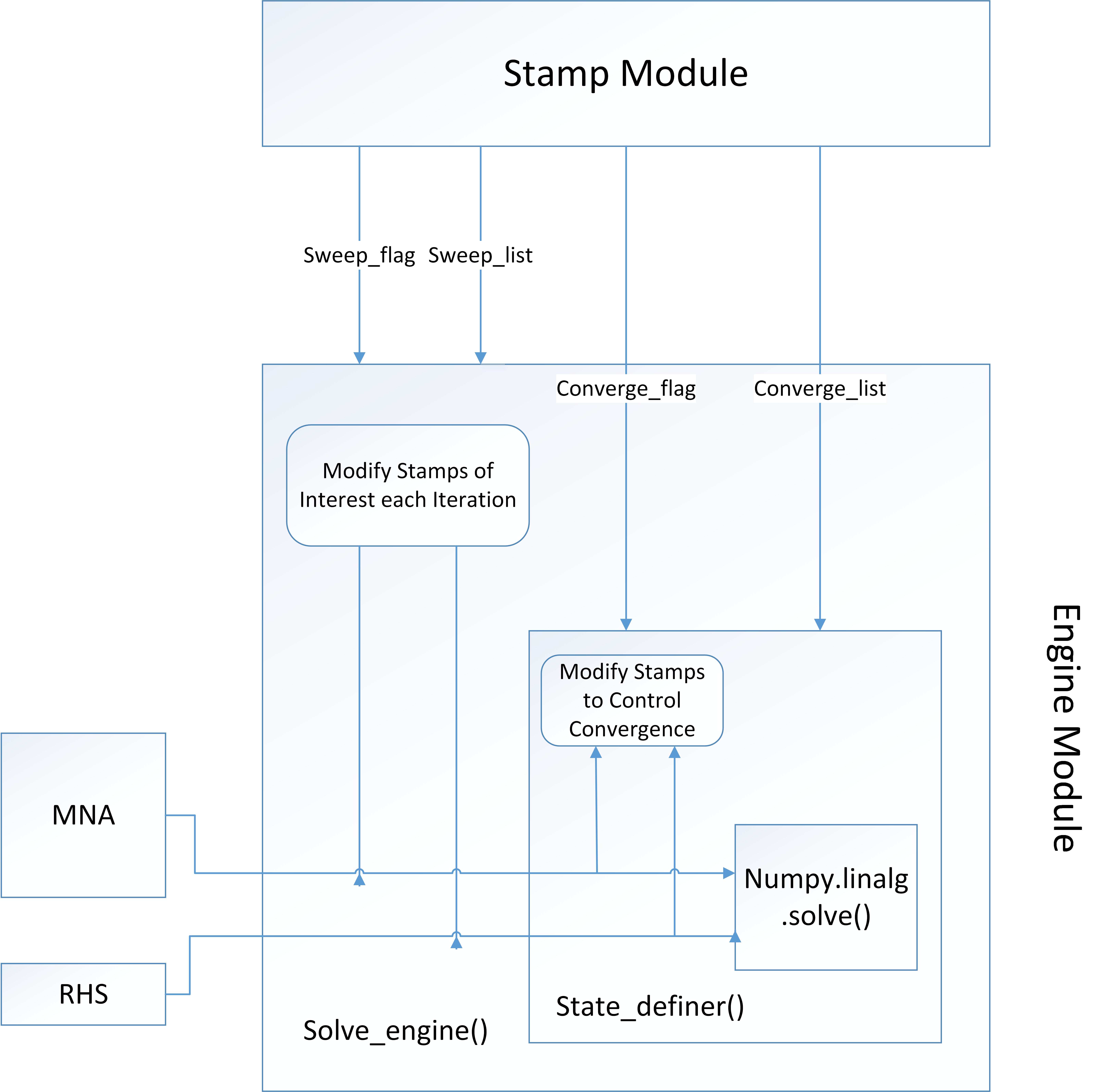
At this phase, different kinds of analysis are abstracted into an uniform model. This model is represent by the sub-module engine. Basically, all kinds of analysis can be constituted by two basic operations: the iterate operation and the converge control operation. While doing a certain analysis, what we are doing is actually solving the circuit on a sequence of consecutive states. Changing the parameters to represents these states is the job of the iterate operation. And in single solving for each states. Converge issue may arise, which means we need to change some parameters and solve the matrix equation several times to make sure the final solution is the real state of the circuit. This falls in the responsibility of the converge control operation. The design of the Engine module are illustrated in figure below

The last package is relatively simple. The solution generated by solver package is the internal representation of the states to the circuit. The last package, called exhibitor is designed to generate the external representation of the states to the circuit required by the user using these internal representations. Also, this package can visualize the result by plotting the waveform of the states of the nodes or the links.